Integrated Package
Software for Multi-copter Flight Simulation
DroneV 5.0
-Wha’s New @V5.0-
By
controlling the rotor tilt angle, multi-copters can achieve six degrees of
freedom (DOF), allowing for independent control of aircraft attitude (yaw,
pitch, roll) and
translational
velocity (X, Y, Z). This dramatically improves flight maneuverability and fault
tolerance compared to the conventional drones with fixed mounting angle rotors.
Ver.
5.0 now supports analysis of variable tilt angle multi-copters, and it is
applicable to the conceptual design and basic performance prediction of manned
eVTOLs or
high-performance
multi-copter type UAVs.
<1> Prediction of
Improvement in Flight Attitude Freedom and Fault Tolerance of Tilt Rotor Type
Multi-copter
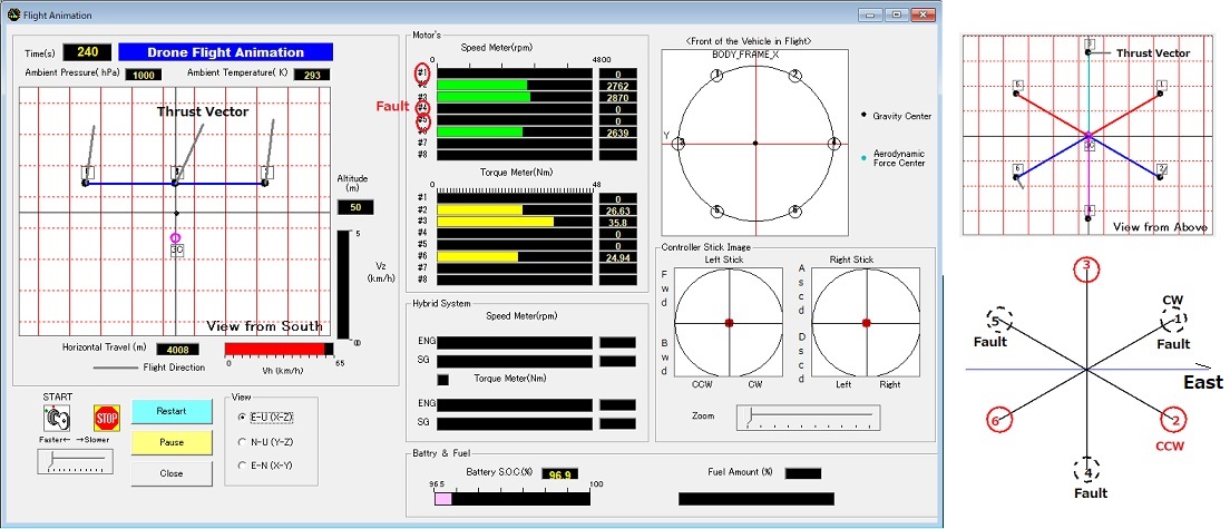
<Analysis Example:
Simulation of a Hexa-copter Flying while Maintaining a Horizontal Attitude with
Three Rotors Losing Their Thrust>
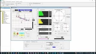
Click on the image to watch the Youtue Movies.
<2> Tilt Rotor Model of DroneV
1.
Tilting
Configurations
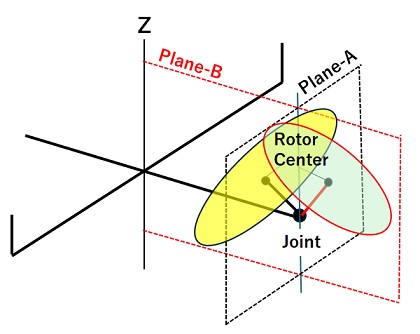
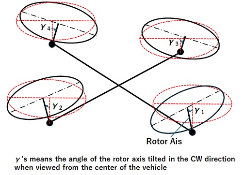
◆Single-Axis Tilting Method
Method -A uses a single actuator attached
to the rotor axis joint to rotate the rotor axis through a tilt angle γ in
Plane-A, a plane perpendicular to the rotor arm.
Method-B can be used to rotate the rotor shaft
through a pitch angle β in Plane-B, a plane formed by the Z axis and rotor arm.
DroneV5.0 uses Method-A because variable tilt
angle offers greater benefits in improving flight performance than Method-B.
However, βs can be defined as fixed values
from the vehicle design specifications.
◆ Dual-Axis Tilting Method
This method uses two actuators on the rotor
axis joint to simultaneously control the tilt angle γ and pitch angle β.
It offers the best flight performance and
fault tolerance, but it also requires more complex mechanisms and controls.
While Drone V5.0 does not support two-axis
variable methods, γ and β can be set as fixed values and input values for each
rotor.
This makes it possible to model and simulate
the conical rotor arrangement used in some eVTOLs.
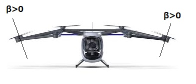
<Figure taken from Web
Contents of Sky-Drive corp.>
2) Kinetics Calculation
Algorithm
・For fixed-rotor multi-copters, the only input
parameter is rotor thrust, and the number of parameters is equal to the number
of rotors. However, for tilt-rotor systems,
each
rotor has two parameters: thrust and tilt angle. This doubles the number of
parameters, making the determination process and algorithm more complex.
・On the other hand, DroneV
uses a proprietary algorithm to determine six parameters related to thrust and
tilt angle distribution for a total of six balance equations,
the balance of forces in the X, Y, and Z directions,
and the balance of moments around the X, Y, and Z axes, to maintain static
equilibrium. Therefore, if the number
of rotors is three or more, the number of
parameters to be determined remains constant at six, regardless of the number
of rotors.
・Furthermore, if a rotor failure leaves only
two rotors operational, the total number of parameters is four: the thrust and
tilt angle of the two rotors, meaning control
with a maximum of four degrees of freedom is
possible. In this case, the four parameters are determined to achieve an
aircraft attitude that maintains a balance between
the moments around the X, Y, and Z axes
and the force along the Z axis of the inertial frame, with the goal of
maintaining altitude without rotation.
-Update History-
Wha’s
New @V4.0
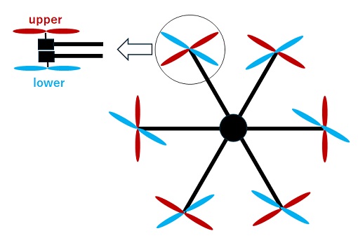
DroneV4.0 supports to simulate the flight
of multi-copters that use contra-rotating rotor unit, which has two rotors
arranged in
upper and lower
stages to obtain large thrust for transporting and delivering goods. The upper
and lower rotors of each rotor set are
each driven by
independent motors to control the vehicle's pitching, rolling, and yawing
attitude, as well as altitude or velocity.

Hexa-copter
with contra rotating rotors Click the Figure Above to Watch the YouTube Movie Click the Figure Above to Watch the YouTube Movie Click
the Figure Above to Watch the YouTube Movie
(1) How to Model the Contra-Rotating Rotor
1.
Thrust Stand Test of the Contra-Rotating Rotor Unit
Measure the thrust , torque, and speed of the upper and lower rotor
using a commercially available or
in-house thrust stand.
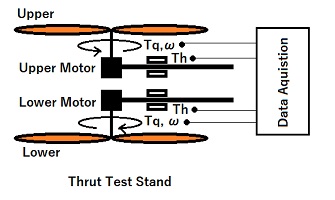
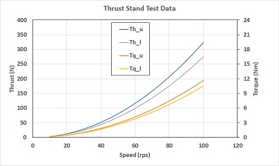
Schematic of Thrust Stand Example
of Thrust Stand Test Data
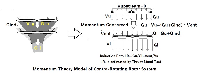
2. Modeling Applying Propeller Momentum
Theory for Contra-Rotating Rotor
Referring to the thrust stand test data
entered in Excel sheet to create the aerodynamic model
of contra-rotating rotor, determine some
parameters in the model.
.
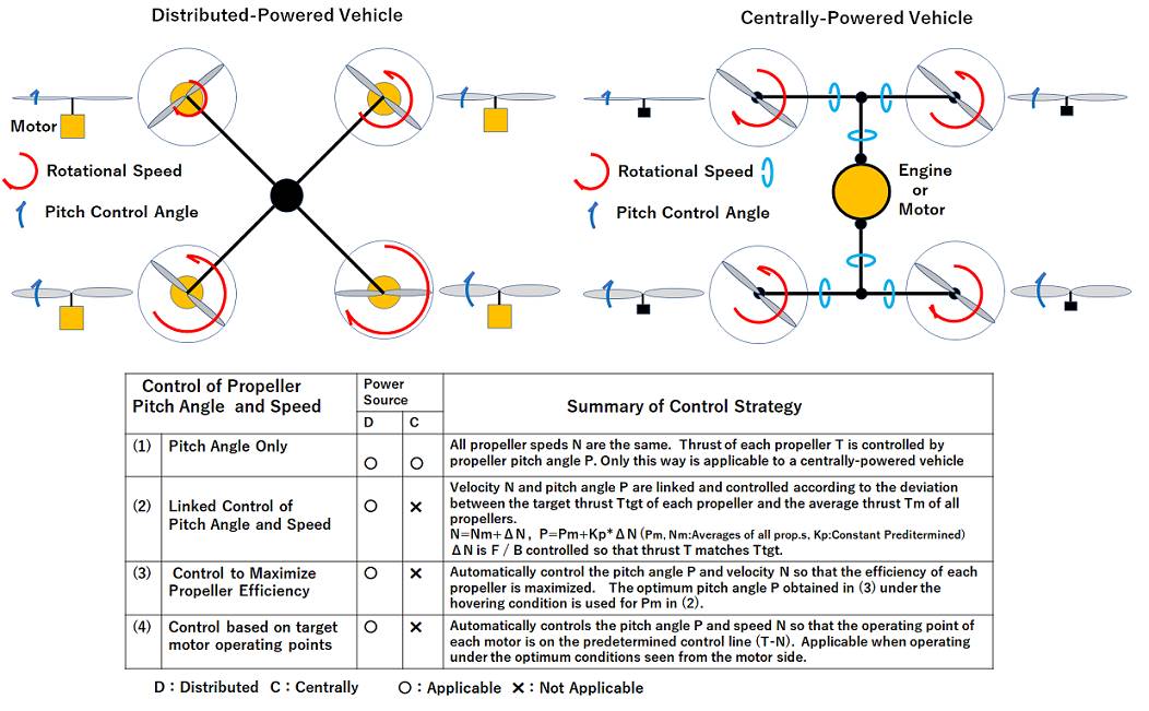
(2) Control of the Rotor Speed
1. Pitching, Rolling, and
Altitude or Velocity of the Vehicle
The
attitude angles except for yawing and altitude of the vehicle are controlled by
the relative difference
in the
total thrust of the upper and lower rotor Thn between each rotor
set.
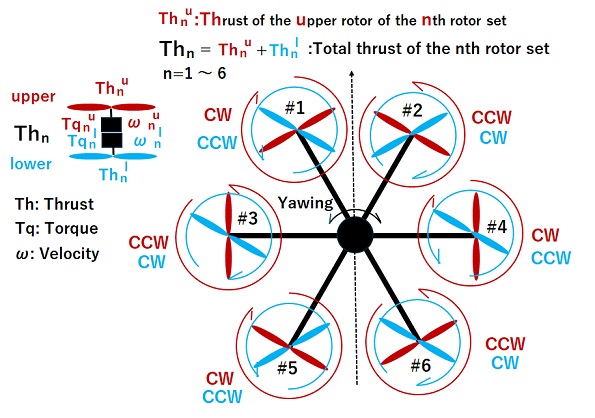
Rotating Motion of All Rotors
in Contra-Rotating Rotor System
2. Yawing
The main purpose of using contra-rotating rotors in airplanes and
helicopters is to cancel the reaction torque of
the two rotors. However, if two rotors with a same pitch are arranged
in series and rotated at a same speed,
differences in thrust and torque between the two rotors will appear.
Therefore, a variable pitch mechanism is
required to solve this problem.
On the other hand, fixed pitch rotors are used in multi-copters in
pursuit of weight reduction and mechanical simplicity,
but the speed can be controlled by an independent motor for each rotor
instead, and Yawing torque can be controlled
by the differential speed of the upper and lower rotors.
The control target is
yawing angular velocity or yawing torque, and the manipulated variable is the
rotational speed
difference Δω between the upper and lower
rotors, and there are three control methods when the target yawing torque
is zero, as shown below.
◆Speed-Based Control
Speed difference Δω = 0, and although the
reaction torque is not balanced for the individual rotor set, the overall
vehicle is balanced.
◆Torque-Based Control
Based on torque difference Δtq=0 to balance the torque in each rotor set, but the speeds of the two rotors are
different.
◆Thrust-Based Control
Thrust difference Δth = 0, and although the
reaction torque is not balanced for the individual rotor set, the overall
vehicle is balanced.
The operating conditions (thrust, speed, and torque) of each rotor will
differ depending on the control methods above.
3. Comparison of Rotor Operating Conditions(Thrust/Speed/Torque) by Yawing Control Method
The simulation results using a Hexa-copter model are shown below.
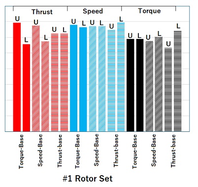
a) Hovering
Figure a) below shows the
operational data of the #1 rotor set when the vehicle with its center of gravity on the
Z-axis is hovering
in a windless environment. Comparing the
upper and lower (U, L) rotors, it can be seen that in
speed-based control, the speed of both
rotors is the same, in torque-based control, the torque is the
same, and in thrust-based control, the thrust is the same as well.
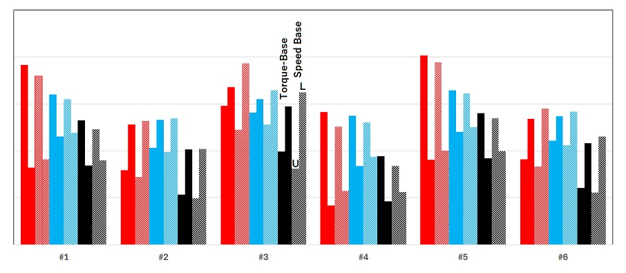
b) Forward Flight
Figure
b) shows the operational conditions of #1 to #6 rotor set when the
vehicle of which center of gravity offset from the Z-axis
flying horizontally forward., using speed-based control or torque-based
control.
In this
case, there are differences in the thrust of each rotor set in
order to control the pitching and rolling attitudes. Then the yawing
torque
is generated due to unbalancing of *drag force acting on each rotor and
gravity acting on the forward-leaning vehicle, and the upper and lower
rotors are differentially operated to maintain the yawing angle.
It can be seen that there are differences in operating
conditions between speed-based control and torque-based control.
*Drag force:
Resistance force which is parallel to the rotor rotational plane and acts in
the opposite direction to the flight direction
a) Hovering
b) Forward Flight
(3) Comparison
of Power Consumption between Contra-Rotating Rotor and Single Rotor
The table below shows a
comparison of the power consumption of a Quad-copter
with contra-rotating rotor and a Octo-copter
with single-rotor, both of which have rotors with the same
specifications.
In
order to
eliminate the effects of losses in the motor and ESC, the total power consumed
by the eight rotor is shown instead of
electric
power consumption in the comparison.
In the
table, it can be noticed that the single rotor consumes about 13-14% less power
in both hovering and forward flight.
Like
this example, if the total rotor rotating area is the same, the rotor
efficiency (N/kW) will generally be higher for a single rotor.
So,
when using contra-rotating rotors, it can be said that consideration on rotor
efficiency by simulations should be made advance.
<Comparison of Power between Contra Rotating and Single>
|
Vehicle
Type |
Num.
of Rotor |
Rotor
Dia. |
Differential
Control Method |
Hovering |
Forward
Flight(10m/s) |
|
Quad-copter |
(Dual)
x (4) =8 |
0.51m |
Speed Base |
5.853kW |
5.423kW |
|
Torque Base |
5.86kW |
5.454kW |
|||
|
Octo-copter |
(Single) x(8)=8 |
0.51m |
− |
5.084kW |
4.655kW |
<Basic Features of the Product>
◆Possible to fly a three-dimensional flight
course while changing the attitude (yaw, pitch, and roll).
-The flight
of vehicle even with complicated flight patterns can be simulated without
detailed programming
such as a motor control, because of applying
an inverse analysis method
◆An impact of the crosswinds defined with a
three-dimensional vector can be predicted.
◆3D coordinates of the center of gravity and
aerodynamic center can be defined, and the allowable center of
gravity position range for safety flight can
be predicted.
◆Flight course can be defined by either time to
X, Y, Z direction velocity component or time to X, Y, Z spatial position.
-In the
case of the course by position input, the specified points can be connected with spline curves, corner R and straight lines, or straight
lines.
Moreover,
the flight speed is automatically determined for each route to pass the
specified position point at the specified time.
Technical
Report
◆Technical
Report: High Power & Low
Emission Engine for Next Generation Hybrid Drone